Because of their important position in the sound system, audio lovers or enthusiasts will be keen to choose a good "DAC", and "decoding" technology is always a topic of interest or debate. Which technology is better, more advantageous and more suitable for everyone to use?
This article simply lists and combs the basic technology of audio DAC and analyzes some hot spots, hoping to provide some useful information or tips to friends who need it, or to dispel some doubts.
"Decoder"Not a decoder.
First of all, let's unify the name and terminology. We are accustomed to call the "decoder" DAC, the English writing is: Digital-To-Analog Converter, which means: digital-analog converter, while the real decoder English writing is: Decoder. In order to unify without misunderstanding, DAC or keep its English abbreviation (DAC) or called digital-to-analog converter (in some cases referred to as converter), commonly known as "decoding" is called digital-to-analog conversion.
1
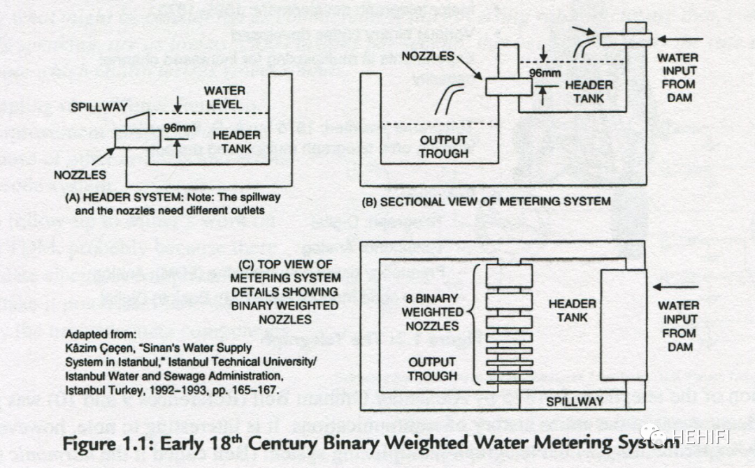
The earliest converters were not electric.
The earliest recorded digital-to-analog converter, probably the binary weighted water measurement system used on the dams of the Ottoman Empire in Turkey in the 18th century, was not in the field of electricity!
Binary weighted water system in the 18th century
The first digital-to-analog conversion of sound is on the telephone line and the sampling frequency is 4kHz.
Since the Telegraph came into being in 1753 and began to develop on a large scale in about 1825, various electronic digital-to-analog conversion technologies have been widely used in communication systems. In 1853, the American inventor M.B.Farmer conceived the concept of time-domain allocated multiplexing (TDM) to use Telegraph lines for time-sharing. After Bell invented the telephone in 1875, in 1903, Willard.M.Miner obtained the American patent of multiplexing technology that uses electromechanical rotary multiplexing switch to sample sound according to the frequency of 4.32kHz or 3.5kHz and then restore it. For telephone lines, it is the first time that someone has applied digital-to-analog conversion to sound.
The earliest PCM had only five bits
Digital-to-analog conversion algorithm. In 1921, Paul M.Rainey of American Western Electric invented PCM (Pulse density Modulation) technology using light and phototube, using only five bits of digital signals. In 1937 Alec Harley Reeves of ITT (France) invented the PCM using electronic tubes and realized the first recorded all-electronic digital-to-analog converter.
The processing technology (implementation method) of digital-to-analog converter has gradually developed from the earliest mechanical, to electromechanical, optoelectronic, vacuum tube, to the use of thin film resistors, transistors, CMOS integrated circuits and now large-scale CMOS integrated circuits (chips). Large-scale integrated circuits give great convenience and space for data processing.
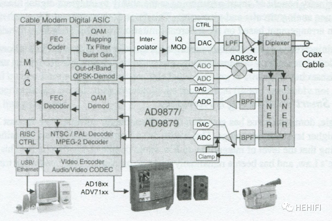
Mixed signal Terminal of ANALOG DEVICES Company in USA
There are many structures of digital-to-analog converters
From the structure of the digital-to-analog converter, the simplest is the serial DAC (also known as Kelvin voltage divider), which adds a series of resistors to the voltage and connects different taps (resistors) through a group of digitally controlled switches to get different output voltages. It was proposed by Lord Kelvin in mid-1800 and only implemented in the 1920s, first with resistors and relays, and then with electronic tubes. This is followed by a list of the evolution of digital-to-analog converters:
Current output divider DAC,
Binary weight resistor DAC,
R2R ladder resistance network DAC,
Segmented DAC,
Oversampling interpolation DAC,
Multiplication DAC,
Predictive nonlinear DAC,
PWM (pulse width modulation) DAC,
Ring serial DAC,
AndSAR(Gradual approach)ADC (Analog to Digital Converter)DAC 、
Sigma-Delta DAC 、
Wait.
The development of technology can be described as a variety of names, the following discussion focus:
2
R2R trapezoidal resistance network DAC
It was first proposed by a man named B.D.Smith in 1953 for digital-to-analog conversion. The core of the technology is to get the value of the output signal through the resistance voltage division, and the resistance voltage network is controlled by digital quantity, so as to realize the conversion from digital quantity to analog quantity.
Typical R2R trapezoidal resistance network (8-bit) structure
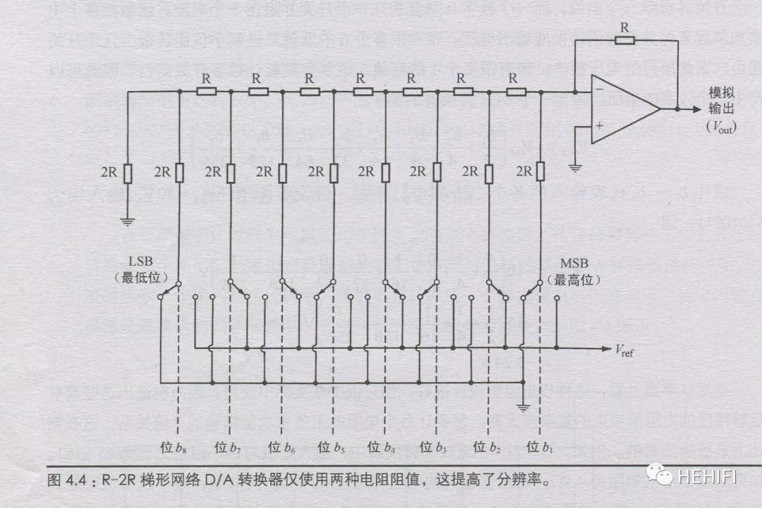
This is an ingenious design, and the resistance value of each resistance circuit (cascade) is half that of the previous circuit, which just realizes the binary weighting operation. Compared with the resistance of the digital-to-analog converter with weighted resistance, the R2R digital-to-analog converter needs only two kinds of resistance, which is simple and reliable.
Now the R2R DAC has a single chip solution (such as TI's PCM1704, manufactured by laser precision correction, the dynamic range can reach 112dB), some use custom modules, or directly implemented on the circuit board (PCB), depending on different designs, the finished DAC of different merchants will be very different. For audio digital-to-analog conversion, due to the very high requirements for conversion operation and resistance precision, there are high requirements in the design scheme and manufacturing process.
TI's PCM1704 (R2R) DAC schematic diagram

Benefits of R2R DAC
1) the resistance is linear
RMel 2R is a representative technology of ancient and traditional PCM digital-to-analog conversion. There must be a reason for its application in high-performance audio digital-to-analog converters: through the partial voltage of the resistor, the resistance is linear in theory, so there is no distortion and extra noise. Here,"The resistance is linear."Became the core concept.
2) avoid oversampling and digital filtering
R2R DAC can carry out digital-to-analog conversion only by switching resistors in the network, without using digital filters such as oversampling, interpolation and decimation, and avoid using digital filters. Some people think that digital filtering will bring the so-called "digital sound" (to be proved).
In this way, you may feel that this technology is very reasonable, but as a traditional digital-to-analog conversion technology, R2R DAC has some problems:
The problem of R2R DAC
1) difference nonlinear error
R2R digital-to-analog conversion represents the analog waveform as an amplitude signal, half the quantization gradient is the accuracy error, the influence of the large signal is not the main, when the signal is small, the influence will become larger and can not be ignored, it will inevitably produce differential nonlinear error, associated with the signal, it will become distortion. Because the degree of nonlinearity changes with the change of signal amplitude, it is more difficult to deal with in the later stage.
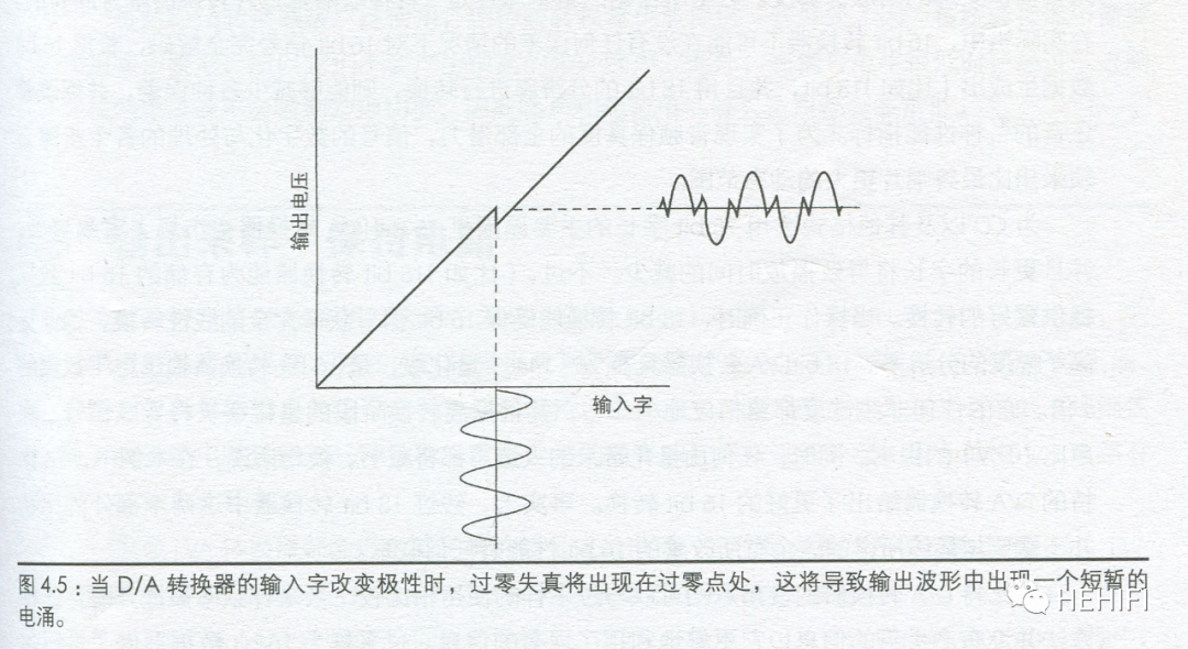
2) Zero-crossing distortion
R2R digital-to-analog conversion will inevitably produce zero-crossing distortion. Whenever the voltage on the highest bit resistance changes (from 0 to 1, or vice versa), it will inevitably cause a change in the polarity of the output voltage (from positive to negative, or vice versa). Due to the existence of resistance error, the simultaneous switching of resistors within the external resistance network will cause differential nonlinear distortion and transient surge at the zero crossing point, resulting in zero-crossing distortion.
Zero-crossing distortion of R2R DAC
3) quantization accuracy
When the depth of digital audio signal is increased by 1 bit, the dynamic range of 6dB will be increased in theory. For R2R DAC, the quantization accuracy will directly determine the maximum dynamic range that DAC can achieve.
Usually CD uses 16-bit digital signal, which has the theoretical dynamic range of 96dB. The amplitude of the lowest bit of the signal is the full amplitude value of 1max 65536 and R2R DAC to deal with such signals. The resistance error of the highest bit should be much less than this ratio, and the signal on the lowest bit is meaningful. Now the error of high precision resistors is 1/1000 Which is equivalent to the lowest bit value of a 10-bit digital signal1/2^10=1/1024), that is to say, if such a high-precision resistor is used as the highest bit of RMI 2R DAC, the digital signals with a depth of more than 10 bits are meaningless, because the signals on those bits are drowned out by the error on the highest bit resistance, and the dynamic range of DAC can not reach 60dB. Now 32-bit digital signals are often played, and the minimum amplitude of the signal is 1 / 2 ^ 32 = 1/4,294,967,296. Therefore, a question is raised: how can the resistive network achieve such accuracy?
For R2R conversion, merchants often try some methods, such as improving the accuracy of resistors in manufacturing, correcting or compensating the resistance network (especially the highest and highest resistors), and so on, to improve the accuracy as much as possible to improve performance. In fact, in order to achieve high-performance audio digital-to-analog conversion, R2R DAC needs to overcome many difficulties.
3
Delta modulation technology marks the beginning of a new era.
In 1950, just like the invention of PCM, which is also the laboratory of ITT in France, Delta (incremental) modulation technology (from quantizing a value to quantifying the increment of a value) was proposed. Although, because of the need for high-frequency support, before the emergence of high-speed digital signal technology, various restrictions prevented the application of this technology (and later Sigma-Delta modulation technology) in high-quality music. At the beginning of a new era of digital audio conversion technology, the technical means have changed from the amplitude of the quantized signal to the change of the quantized signal, and the focus has also shifted from amplitude to time.
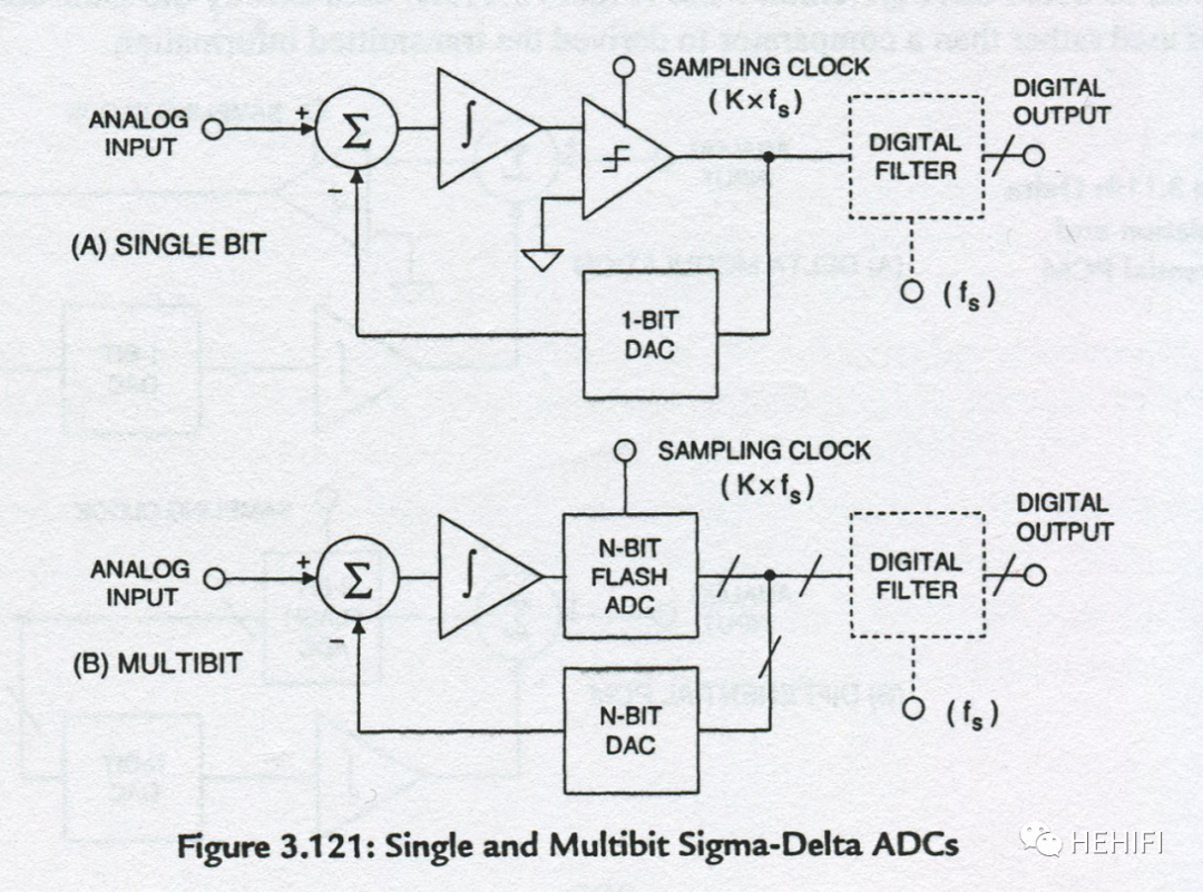
Sigma-Delta DAC
In the same year, C.C.Cutler of Bell telephone Laboratory in the United States also obtained the patent of differential PCM modulation technology (Delta modulation can be regarded as a simple form of differential PCM modulation). In 1952 and 1953, the Phillips laboratory in the Netherlands discovered the same principle and provided many 1-bit and multi-bit research results. In 1954, Cutler obtained a very meaningful patent for oversampling and noise shaping. In 1962, the improved Delta-Sigma (mainly adding Sigma- integral) technology based on Delta modulation was formally proposed by Inose, Yasuda and Murakami. In the 1970s, AT&T engineers changed it to Sigma-Delta (perhaps more correct). Since then, digital audio technology has officially entered the Sigma-Delta era.
Sigma-Delta uses low-bit (1-bit) quantization and high-speed sampling technology, which is simply described as comparing the difference between the sampled input signal and the previously sampled cumulative quantized signal (Delta), the difference obtained after comparison (to determine whether to increase or decrease, if it is 1-bit quantization, it is 1 or 0), and then added to the last cumulative quantization difference (Sigma) Then the digital quantity of the audio signal encoded by PCM is formed, and the waveform of the input signal is well tracked by high sampling frequency.
Digital-to-analog conversion is the reverse operation of this process.
Sigma-Delta technical diagram
Modern digital-to-analog conversion chips, such as the famous TI's PCM1794,Cirrus Logic's CS4398,AKM 's AK4490, use this technology, and companies may only make some changes based on this technology to achieve the purpose of differentiation.
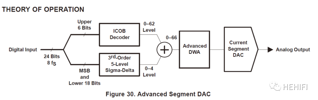
An Application of segmented DAC
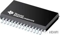
As an example of differentiation, TI added segmented modulation on the basis of Sigma-Delta modulation to decompose the original multi-bit digital signal into high and low parts (segments). Because their functions and effects are different, they can be processed separately according to different purposes. PCM1794 digital-to-analog converter chips are designed to achieve excellent dynamic performance and improve tolerance for Jitter (jitter).
PCM1794 Digital to Analog Converter Chip of TI
PCM1794 digital-to-analog conversion schematic
Sigma-Delta is an alternative to R2R.
Sigma-Delta digital-to-analog conversion technology is an alternative to traditional PCM (quantized by amplitude) digital-to-analog conversion. Compared with the previous Rmur2R technology, Ken.C.Pohlmann of the United States has a visual description in his book Digital Audio Technology (6th edition):
"The traditional trapezoidal resistance network converter is like a row of light bulbs, each connected to a switch. For example, there are 16 light bulbs, each with a different brightness, and you can achieve 2 ^ 16 or 65536 different brightness levels by lighting different combinations. However, the difference in the light intensity of each bulb will introduce errors in the output brightness level. Any particular combination of switches may not accurately produce the desired brightness. Similarly, trapezoidal resistor network converters introduce errors when trying to reconstruct audio signals.
Sigma-Delta technology takes a completely different approach. Instead of using multiple light bulbs and switches, it uses only one light bulb and one switch, simply depending on the light bulb on and off to change the brightness. For example, if the light bulb is constantly switched between on and off, and the length of time between on and off is equal, the output is half the brightness. If the light bulb lights up for longer, the brightness will also increase. Similarly, ideally the Sigma-Delta converter can represent the audio amplitude in 1 bit, using only very fast switching and very precise timing. Sigma-Delta technology itself is an accurate method to represent audio waveforms."
Or, to more simply describe the most fundamental difference between the two, R2R digital-to-analog conversion takes the amplitude quantization as the baseline, while Sigma-Delta uses time as the baseline to keep the amplitude unchanged (1-bit modulation) or basically unchanged (multi-bit modulation: generally 4-bit 6-bit).
Because of this, Sigma-Delta technology can overcome the shortcomings of R2R digital-to-analog conversion technology. The main advantages are:
1)Improve the accuracy of quantization and keep the same accuracy in different amplitudes, the error is not related to the signal itself, that is, noise, which can be easily processed in the later stage.
2)The signal is divided only in time, so there is no zero-crossing error (distortion).
3)Through oversampling (interpolation), digital filtering (decimation) and noise shaping, the noise in the audio range can be reduced, and the dynamic range can easily reach the level above 120dB.
4)The use of brick-wall analog filters is avoided to minimize phase shift and distortion.
Key points of Sigma-Delta conversion Technology
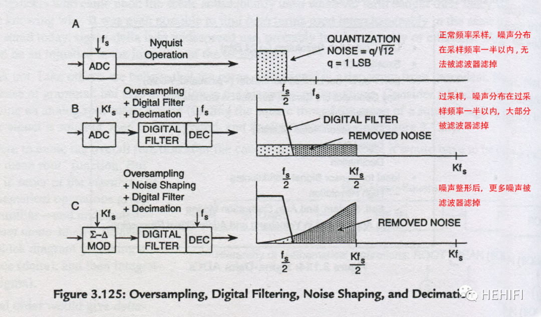
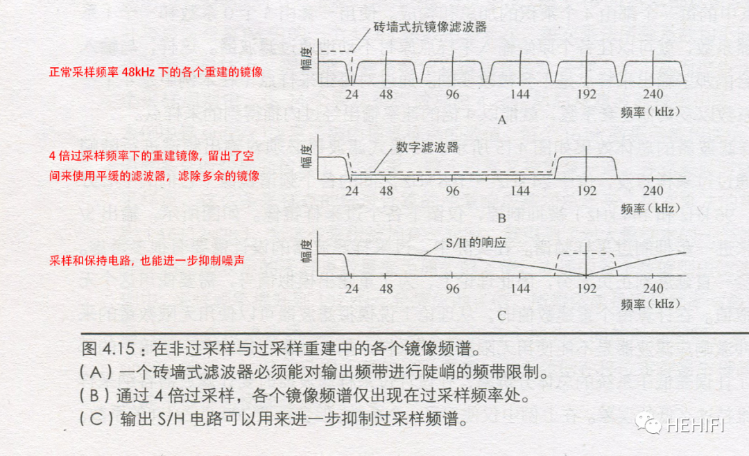
Sigma-Delta technology increases the Nyquist frequency by many times higher than the normal sampling frequency. The sampling theorem stipulates that the Nyquist frequency should not be less than twice the highest frequency of the sampled signal. For audio, that is, 40kHz. For example, CD uses the sampling frequency of 44.1kHz, leaving some margin. Under oversampling, the Nyquist frequency can be as high as hundreds of kHz or higher, and the digital filter clears up a large space between the Nyquist frequency and the audio frequency band, and the noise after shaping is maximized to the frequency band above the Nyquist frequency, which allows a simple and gentle low-order analog filter to easily filter out the unwanted noise while maximizing the amplitude and phase of the signal without being affected.
Effects of oversampling and digital filtering
Countermeasures to overcome the shortcomings:
1) background noise
In Sigma-Delta technology, 1-bit quantization itself is linear, but the background noise will be relatively high. If multi-bits (such as 4 bits) are used, the background noise can be reduced, but it will lead to distortion caused by component mismatch. One solution is to rotate inconsistent components randomly through dynamic element adaptation (DEM) technology, so that the average mismatch error can be reduced to close to zero, and the mismatch (distortion) can be transformed into in-band noise, and then through shaping, the noise can be transferred out of band, and the dynamic range can still be maintained at a high level. This generally requires the chipmaker to make subsequent arrangements.
2) Nonlinearity in frequency domain
It can be understood as the phenomenon of inconsistent behavior at different frequencies. ESS Company of the United States proposed that in the frequency domain simulation, the Sigma-Delta modulator is a very nonlinear system, which can only give a general performance. One is described asModulation depth problem: Most Sigma-Delta modulations cannot achieve 100% modulation depth (full amplitude can only be up to 50%), and the DC component generated when the modulation depth is deepened will lead to increased noise; the other isTransient nonlinear problems in noise shaping:When the signal changes rapidly, the feedback circuit of noise shaping will show transient nonlinear behavior.
ESS company also gives a solution, different designs of Sigma-Delta modulator in detail, cascade independent and stable low-order modulator, carefully select the relative gain of the integrator region, so that the occurrence of clipping can be well controlled. In this way, when the modulation depth is close to 100%, all the low-order modulators are stable, and the modulators of the Sabre series DAC (such as ES90xx, ES90xxPRO DAC chips) under the HyperStream trademark of ESS can reach a modulation depth of 90% of the full amplitude, so as to deal with the above problems.
4
DSD was originally archived.
One more thing to say is DSD. Initially, DSD was not used as a provisionable format. In 1988, Sony acquired CBS/Columbia Records and obtained a large number of excellent tape recordings. Sony wants to convert all tape files into digital format files, but it is not sure when the new format will be released in the future, nor can it determine the number of digits and frequency of the new format. In order to maintain flexibility, it uses a new 1-bit format, which is later known as DSD, that is, Direct Stream Digital: direct stream digital.
DSDAndPCMThe relationship between
PCM is a general audio signal format, which mostly uses Sigma-Delta modulators to modulate and encode audio signals into pulse density modulation (PCM) digits (16, 20, 24 or 32 bits), arranged in chronological order. Sampling frequency determines the arrangement density of digital quantities in time. CD was introduced in 1981, and the audio format is 16-bit digital and 44.1kHz sampling frequency.
DSD is another audio signal format, which uses a very high frequency to modulate and encode the audio signal into a 1-bit pulse density modulation (PCM) digital quantity using a Sigma-Delta modulator.. In 1999, Phillips and Sony introduced SACD (Super Audio CD) using a 1-bit DSD code (dual-channel or multi-channel) with a sampling frequency of 2.8224MHz.Compare the 16-bit digital and 44.1kHz sampling frequencies of CDIn SACDThe bit rate of DSD signal is four times that of CD.
As can be seen from the above, DSD and PCM actually belong to PCM, but the current customary terms of address have different meanings.
With the diversification of storage media, audio formats are no longer limited to CD or SACD standards, there are more choices, corresponding toDSD signals can also be converted into a variety of standard PCM signals. The following table shows the convertible relationships at common sampling frequencies:

Advantages of DSD
1)DSD canThe dynamic range of 120dB in audio band and the flat frequency response of 100kHz are realized.
2)DSD uses high sampling frequency, such as SACD 2.8224MHz Nyquist frequency is also very high 1.4112MHz, so there is no need for decimation filtering and PCM quantization in the recording process.And you don't need to be inOversampling (interpolation) digital filter is used in the playback process, and it can be played directly without even going through digital-to-analog conversion.
3)Using a simpler converter, you can reduce theThe cost of playing the device.
The deficiency of DSD
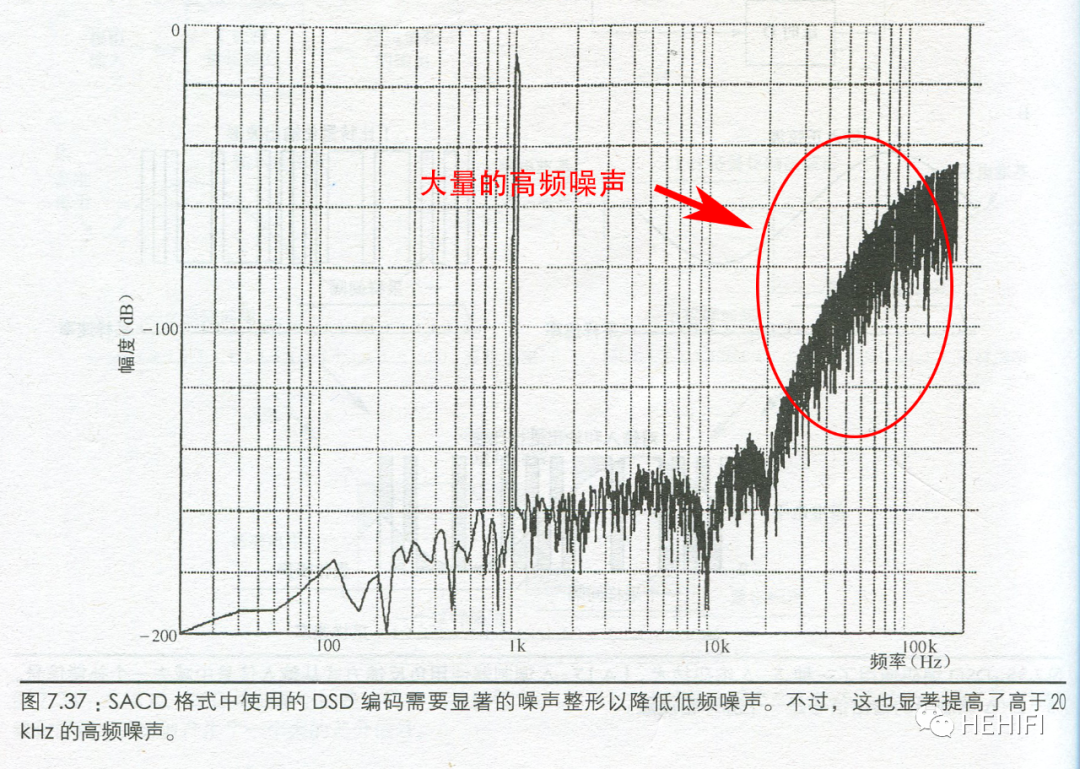
1) noise
The DSD signal contains a large number ofHigh frequency noise, which is a significant noise shaping component, is distributed in the frequency band above 20kHz. If it is played directly without processing, in theory, the human ear will filter out the content outside the audio band and will not affect the sense of hearing. in fact, the analog amplifier used for playback will produce nonlinear modulation because of these signals, resulting in components in the audio band, affecting the signal in the band, or these large numbers of high-frequency components will cause the amplifier or loudspeaker to enter abnormal states such as overload and saturation. For example, after converting the DSD signal into an analog signal, try to filter out these high-frequency components for processing, then in the limited frequency band space to filter out a large number of these high-frequency noise, we need to use a steeper high-order analog filter, which will inevitably bring serious phase shift of the signal in the frequency band.
Noise Spectrum of DSD signal
2) difficult to deal with
DSD is a 1-bit digital signal, which can not be processed theoretically, for example, by adding jitter (Dither) to optimize performance, such as using other alternative methods. Will become very complex (need to convert 1-bit signal into signals such as 8-bit DSD-wide or other depth signals and then perform complicated conversion processing) and require more processing power of the processor (greater density of DSD signals require greater processing power), some processing may not be possible.
3) limitations of converters
When DSD was introduced, the best performance converter was the 1-bit Sigma-Delta converter, and the DSD naturally adopted the 1-bit format, and the subsequent multi-bit Sigma-Delta converter had better dynamic range performance. as a result, many DSD systems using earlier technologies were inferior to many modern PCM systems in performance.
4) distortion
Signal distortion is the biggest problem in DSD. DSD adopts a 1-bit signal format, so noise shaping is difficult to be really effective in a 1-bit system. In fact, the noise after shaping is related to the signal, which becomes the inherent distortion in the signal.
5
Is FPGA an alternative to the next generation?
Recently, FPGA has become a hot spot of audio processing. Since the American company Xilinx launched the first product in the world in 1985, FPGA is a hot new technology, its essence is logic circuit, the combination of logic circuit can be changed by software, because the signal is operated directly by hardware, soSpeedThan ordinary chips (chips that require software computing, such as CPU)Much faster.
FPGA can be understood as a processing technology, that is, a means to implement a technology, not a technology itself.For audio digital-to-analog conversion, the audio modulation algorithm needs to be realized by FPGA programming, including a series of audio processing questions, all of which need the new processing technology of FPGA to answer.
There are other ways to use FPGA and Rmur2R ladder resistance network to achieve more complex or higher performance of R2R digital-to-analog conversion, and some use FPGA for digital signal shaping to reduce the influence of Jitter (time base jitter).
As a new hot spot, the core question is: will the performance of digital-to-analog conversion realized by FPGA chip be better than that realized by special digital-to-analog conversion chip?What breakthroughs can this processing technology (means) bring to audio conversion technology? Or solve what problem? It is foreseeable that FPGAs may bring benefits in terms of signal processing capabilities. At present, there seems to be no unified statement for these. In terms of solutions to a series of problems such as audio modulation and conversion, we shouldThere is no clear model yet. Therefore, the effect is difficult to judge, and it is difficult to discuss further here.
6
Summary
In order to achieve high-quality audio conversion performance, R2R converters need to solve many problems; it is unknown whether a universal FPGA chip can outperform a dedicated converter chip; Sigma-DeltaIn the more than 70 years since its invention, it has been the most advanced audio conversion technology. The progress from one bit to multiple bits has further improved the performance of the converter.TodayIt still has a dominant position in the field of high-quality music. With the advancement of semiconductor (chip) processing technology, the density of available digital audio signals is also increasing. The performance of converters may no longer be a problem in the future. There may be more possibilities in the future. We will wait and see.
If there are any errors, supplements or different opinions, please point them out.
2021.02.01
Reference materials:
1. (C) The Data Conversion Handbook, ANALOG DEVICES, Walt Kester, Editor, ELSEVIER 2005;
2. Digital Audio Technology (6th Edition)[United States] by Ken.C.Pohlmann, translated by Xia Tian, People's Posts and Telecommunications Press 2012;
3. Digital Audio Explained For the Audio Engineer by Nika Aldrich, Second Edition, Sweetwater Sound Inc, 2005;
4. PCM1704, 24-Bit, 96kHz BiCMOS Sign-Magnitude DIGITAL-TO-ANALOG CONVERTER,Burr-Brown Corporation, February, 1999;
5. PCM1794A, 24-BIT, 192-kHz SAMPLING, ADVANCED SEGMENT, AUDIO STEREO DIGITAL-TO-ANALOG CONVERTER, Texas Instruments, NOVEMBER 2006;
6. CS4398, 120 dB, 192 kHz Multi-Bit DAC with Volume Control, Cirrus Logic, Inc. 2005;
7. AK4490EN Premium 32-Bit 2ch DAC, AsahiKASEI, 2015/12;
8. Technical Details of the Sabre Audio DAC, Martin Mallinson and Dustin Forman, ESS Technology Technical Staff;
9. DEVICE AND METHOD FOR SIGNAL PROCESSING, US Patent 7,058,464B2, Jun. 6, 2006.